Product Description:
|
Product name:
|
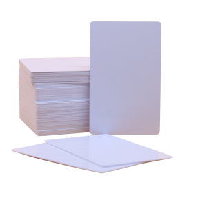
HJ RFID card
|
|
Material:
|
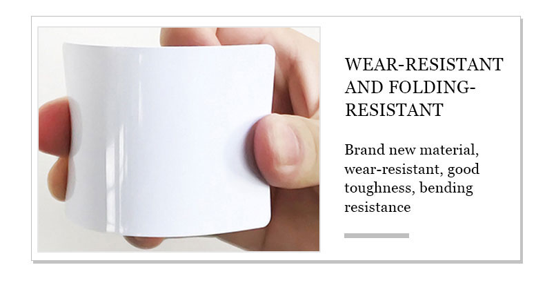
High quality PVC、 PET 、PETG、ABS、Transparent PVC、 wood etc
|
|
Size:
|
85.5*54*0.9 mm
|
|
Printing:
|
Offset printing, Digital printing, Silk screen printing, and Customized
|
|
Surface Effect:
|
Glossy/Matte/Frosted Finish
|
|
Frequency:
|
LF 125KHz、HF 13.56MHz、UHF 840-960MHz
|
|
RFID Chip:
|
*HF 13.56MH, Ntag215
Please consult our customer office for more chips. |
|
Contact IC Chip:
|
SLE4442, SLE4428, 24C16 etc. Please consult our customer office for more chips.
|
|
Magnetic Stripe:
|
300oe/600oe/2750oe; Color: Black/Gold/Silver
|
|
Crafts:
|
Custom printing Logos & Number, Laser Serial Number, UID number,
Chip encoding , Anti-metal layer , Back adhesive , Epoxy cover |
|
Coding:
|
Laser, series number, QR code, Bar code etc.
|
|
Packaging
|
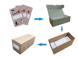
Standard size card packing: 1000pcs/inner box, 10000pcs or 20000pcs/ctn.Irregular size(except the standard size), normal we packed
50-100pcs/Opp bag and then in carton, or packed per your request |
Rfid card working principle:
The basic working principle of RFID technology is not complicated: After the tag enters the reader, it receives the radio frequency signal from the reader, and uses the energy obtained by the induced current to send out the product information stored in the chip (Passive Tag, passive tag or passive tag). ), or the tag actively sends a signal of a certain frequency (Active Tag, active tag or active tag), the reader reads and decodes the information, and then sends it to the central information system for relevant data processing.
A complete RFID system is composed of a reader and an electronic tag, which is a so-called transponder and an application software system. Its working principle is that the reader emits radio wave energy of a specific frequency to The drive circuit sends out the internal data. At this time, the Reader receives and interprets the data in sequence and sends them to the application program for corresponding processing.
From the perspective of the communication and energy sensing methods between the RFID card reader and the electronic tag, it can be roughly divided into two types: inductive coupling and backscatter coupling. Generally, low-frequency RFID mostly adopts the first method, and high-frequency RFID mostly adopts the second method.
The reader can be a read or read/write device depending on the structure and technology used, and it is the information control and processing center of the RFID system. The reader usually consists of a coupling module, a transceiver module, a control module and an interface unit. The reader and the tag generally adopt a half-duplex communication mode for information exchange, and the reader provides energy and timing to the passive tag through coupling. In practical applications, management functions such as the collection, processing and remote transmission of object identification information can be further realized through Ethernet or WLAN.
component:
The complete RFID system consists of three parts: Reader, Tag and data management system.
- About the reader
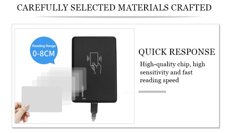
The reader is a device that reads the information in the tag or writes the information that the tag needs to store into the tag. Depending on the structure and technology used, the reader can be a read/write device, which is the information control and processing center of the RFID system. When the RFID system is working, the reader sends radio frequency energy in an area to form an electromagnetic field, and the size of the area depends on the transmit power. The tag in the coverage area of the reader is triggered to send the data stored in it, or modify the data stored in it according to the instructions of the reader, and can communicate with the computer network through the interface. The basic composition of the reader usually includes: transceiver antenna, frequency generator, phase-locked loop, modulation circuit, microprocessor, memory, demodulation circuit and peripheral interface composition.
(1) Transceiver antenna: Send radio frequency signals to the tag, and receive the response signal and tag information returned by the tag.
(2) Frequency generator: Generates the operating frequency of the system.
(3) Phase-locked loop: Generate the required carrier signal.
(4) Modulation circuit: Load the signal sent to the tag to the carrier wave and send it out by the radio frequency circuit.
(5) Microprocessor: Generates the signal to be sent to the label, decodes the signal returned by the label, and sends the decoded data back to the application program. If it is an encrypted system, a decryption operation is also required.
(6) Memory: store user programs and data.
(7) Demodulation circuit: demodulate the signal returned by the tag and deliver it to the microprocessor for processing.
(8) Peripheral interface: to communicate with the computer.
- About electronic tags
The electronic tag consists of a transceiver antenna, AC/DC circuit, demodulation circuit, logic control circuit, memory and modulation circuit.
(1) Transceiver antenna: Receive the signal from the reader and send the required data back to the reader.
(2) AC/DC circuit: Utilize the electromagnetic field energy emitted by the reader, output by the voltage regulator circuit to provide a stable power supply for other circuits.
(3) Demodulation circuit: Remove the carrier from the received signal and demodulate the original signal.
(4) Logic control circuit: decode the signal from the reader, and send back the signal according to the requirements of the reader.
(5) Memory: As a location for system operation and storage of identification data.
(6) Modulation circuit: The data sent by the logic control circuit is loaded to the antenna and sent to the reader after the modulation circuit.
Our company:

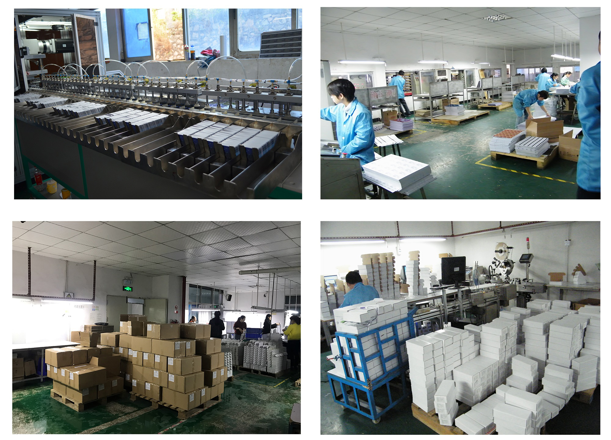
Our workshop:
